 |
||
| Home | Login | Schedule | Pilot Store | 7-Day IFR | IFR Adventure | Trip Reports | Blog | Fun | Reviews | Weather | Articles | Links | Helicopter | Download | Bio | ||
Site MapSubscribePrivate Pilot Learn to Fly Instrument Pilot 7 day IFR Rating IFR Adventure Commercial Pilot Multi-Engine Pilot Human Factors/CRM Recurrent Training Ground Schools Articles Privacy Policy About Me Keyword:  |
<< Previous | Next
(continued)
>>
Chapter 11. HELICOPTER FLIGHT
MANEUVERS (continued)
AUTOROTATIONS In helicopter flying, an autorotation is a maneuver that can be performed by the pilot whenever the engine is no longer supplying power to the main rotor blades. A helicopter transmission is designed to allow the main rotor to rotate freely in its original direction if the engine stops. At the instant of engine failure, the blades will be producing lift and thrust from their angle of attack and velocity. By immediately lowering collective pitch (which must be done in case of engine failure), lift and drag will be reduced, and the helicopter will begin an immediate descent, thus producing an upward flow of air through the rotor system. The impact of this upward flow of air on the rotor blades produces a "ram" effect which provides sufficient thrust to maintain rotor RPM throughout the descent. Since the tall rotor is driven by the main rotor during autorotation, heading control can be maintained as in normal flight. Several factors affect the rate of descent in autorotation - air density (density altitude), gross weight, rotor RPM, and airspeed. The pilot's primary control of the rate of descent is the airspeed. Higher or lower airspeed is obtained with the cyclic control just as in normal flight. A pilot has a choice in angle of descent varying from vertical descent to maximum range (minimum angle of descent). Rate of descent is high at zero airspeed and decreases to a minimum somewhere in the neighborhood of 50 to 60 miles per hour, depending upon the particular helicopter and the factors just mentioned. As the airspeed increases beyond that which gives minimum rate of descent, the rate of descent increases again. When an autorotative landing is to be made, the energy stored in the rotating blades can be used by the pilot to decrease the rate of descent and make a safe landing. A greater amount of rotor energy is required to stop a helicopter with a high rate of descent than is required to stop a helicopter that is descending more slowly. It follows then that autorotative descents at very low or very high airspeeds are more critical than those performed at the proper airspeed for the minimum rate of descent. Each type of helicopter has a specific airspeed at which a power-off glide is most efficient. The best airspeed is the one which combines the most desirable (greatest) glide range with the most desirable (slowest) rate of descent. The specific airspeed is somewhat different for each type of helicopter, yet certain factors affect all configurations in the same manner. For specific autorotation airspeeds for a particular helicopter refer to the helicopter flight manual. The specific airspeed for autorotations is established for each type of helicopter on the basis of average weather and wind conditions, and normal loading. When the helicopter is operated with excessive loads in high density altitude or strong gusty wind conditions, best performance is achieved from a slightly increased airspeed in the descent. For autorotations in light winds, low density altitude, and light loading, best performance is achieved from a slight decrease in normal airspeed. Following this general procedure of fitting airspeed to existing conditions, a pilot can achieve approximately the same glide angle in any set of circumstances and estimate the touchdown point. When making turns during an autorotative descent, generally use cyclic control only. Use of antitorque pedals to assist or speed the turn causes loss of airspeed and downward pitching of the nose - especially when left pedal is used. When the autorotation is initiated, sufficient right pedal pressure should be used to maintain straight flight and prevent yawing to the left. This pressure should not be changed to assist the turn. If rotor RPM becomes too high during an autorotative approach, collective pitch should be raised sufficiently to decrease RPM to the normal operating range, then lowered all the way again. This procedure may be repeated as necessary. If the throttle has not been closed in practice autorotations, it will be necessary to reduce it as collective pitch is raised; otherwise, the engine and rotor will reengage. After the collective is lowered, the throttle should be readjusted to maintain a safe engine RPM. RPM is most likely to increase above the maximum limit during a turn due to the increased back cyclic stick pressure which induces a greater airflow through the rotor system. The tighter the turn and the heavier the gross weight, the higher the RPM will be. HOVERING AUTOROTATION As the name implies, hovering autorotations are made from a hover. They are practiced so that a pilot will automatically make the correct response when confronted with engine stoppage or certain other inflight emergencies while hovering. TECHNIQUE:
A no-flare autorotation can be used when the selected landing area is sufficiently long and smooth to permit a surface run. Practice no-flare autorotations may be made as follows. TECHNIQUE:
 FLARE AUTOROTATION FLARE AUTOROTATION A flare autorotation (see figure 77 to the right) enables the pilot to land a helicopter at any speed between that resulting in little or no landing run, up to that of a no-flare autorotation; that is, anywhere between a zero groundspeed and the speed of touchdown resulting from a no-flare autorotation. The speed at touchdown and the resulting ground run will depend on the rate and amount of the flare - the greater the degree of flare and the longer it is held, the slower the touchdown speed and the shorter the ground run. The slower the speed desired at touchdown, the more accurate must be the timing and speed of the flare, especially in helicopters with low inertia rotor systems. TECHNIQUE:
A power recovery is used to terminate practice autorotations at a point prior to actual touchdown. After the power recovery, a landing can be made or a go-around initiated. TECHNIQUE:
 RAPID
DECELERATION OR QUICK STOP RAPID
DECELERATION OR QUICK STOP Although used primarily for coordination practice, decelerations (see figure 78 to the right) can be used to make a quick stop in the air. The purpose of the maneuver is to maintain a constant altitude, heading, and RPM while slowing the helicopter to a desired groundspeed. The maneuver requires a high degree of coordination of all controls. It is practiced at an altitude that will permit a safe clearance between the tail rotor and the surface throughout the maneuver, especially at the point where the pitch attitude is highest. The altitude at completion should be no higher than the maximum safe hovering altitude prescribed by the manufacturer. In selecting an altitude at which to begin the maneuver, the overall length of the helicopter and the height-velocity chart must be considered. Although the maneuver is called a rapid deceleration or quick stop, this does not mean that it should be rushed to completion. The rate of deceleration is at the discretion of the pilot. A quick stop is completed when the helicopter comes to a hover during the recovery. TECHNIQUE:
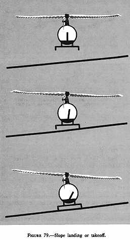
The approach to a slope is similar to the approach to any other landing area. During slope operations, allowance must be made for wind, barriers, and forced landing sites in case of engine failure. Since the slope may constitute an obstruction to wind passage, turbulence and downdrafts must be anticipated. Slope landing Usually, a helicopter should be landed on a cross-slope rather than on an upslope. Landing downslope or downhill is not recommended because of the possibility of striking the tail rotor on the surface. TECHNIQUE:
 COMMON ERRORS: COMMON ERRORS:
The procedure for a slope takeoff is almost the exact reverse of that for a slope landing (see figure 79 to the right). TECHNIQUE:
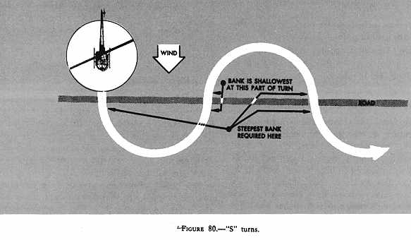
Recovery from low rotor RPM is a procedure used to return to the normal rotor operating RPM. This recovery procedure, if performed properly, will normally regain lost rotor RPM while still maintaining flight. A low rotor RPM condition is the result of having an angle of attack on the main rotor blades (induced by too much upward collective pitch) that has created a drag so great that engine power available, or being utilized, is not sufficient to maintain normal rotor operating RPM. When a low rotor RPM condition is realized, immediately lower the collective pitch. This action will decrease the angle of attack of the main rotor blades which, because of reduced rotor drag, will momentarily relieve excessive engine load. This action will also cause the helicopter to settle because some lift will be lost. As the helicopter begins to settle, smoothly raise the collective pitch just enough to stop the settling motion. This procedure, under critical conditions, may have to be repeated to regain normal rotor RPM or, if terrain permits, a landing may be necessary to restore the RPM. When operating at sufficient altitudes above the surface, however, it may be necessary to lower the collective pitch only once to regain sufficient rotor RPM. The amount that the collective pitch can be lowered will depend on the altitude available at the time the low rotor RPM condition occurs. When hovering near the surface, the collective pitch should be lowered cautiously to preclude hard contact with the surface. When the RPM begins to increase and attains approximately normal rotor operating RPM, anticipate decreasing the throttle slowly to prevent the engine from overspeeding. If recovery from a low rotor RPM condition is not made soon enough, lifting power of the main rotor blades will be lost, including pedal effectiveness. Pedal ineffectiveness occurs as a result of the loss of tail rotor RPM because the tail rotor RPM is directly proportional to the main rotor RPM. If pedal effectiveness is lost, and the altitude is such that a landing can be made before the turning rate increases dangerously, decrease collective pitch slowly, maintain a level attitude with cyclic control, and land.  "S" TURNS "S" TURNS "S" turns present one of the most elementary problems in the practical application of the turn and in the correction for wind drift in turns. The reference line used, whether a road, railroad, or fence, should be straight for a considerable distance and should extend as nearly perpendicular to the wind as possible. The object of "S" turns is to fly a pattern of two half circles of equal size on opposite sides of the reference line (see figure 80 to the right). The maneuver should be started at an altitude of 500 feet above the terrain and a constant altitude maintained throughout the maneuver. "S" turns may be started at any point. However, during early training, it may be beneficial to start on a downwind heading. Entering downwind permits the immediate selection of the steepest bank that is desired throughout the maneuver. The discussion that follows is based on choosing a reference line that is perpendicular to the wind and starting the maneuver on a downwind heading. As the helicopter crosses the reference line, a bank is immediately established. This initial bank will be the steepest used throughout the maneuver since the helicopter is headed directly downwind. The bank should be gradually reduced as necessary to describe a ground track of a half circle. The turn should be timed so that, as the rollout is completed, the helicopter is crossing the reference line perpendicular to it and headed directly upwind. A bank is immediately entered in the opposite direction to begin the second half of the "S." Since the helicopter is on an upwind heading, this bank (and the one just completed before crossing the reference line) will be the shallowest in the maneuver. It should be gradually increased as necessary to describe a ground track which is a half circle identical in size to the one previously completed on the other side of the reference line. The steepest bank in this turn should be attained just prior to rollout (when the helicopter is approaching the reference line nearest to a downwind heading). This bank, along with the initial bank entered at the beginning of the maneuver, will be the steepest bank used in "S" turns. The turn should be timed so that, as the rollout is completed, the helicopter is crossing the reference line perpendicular to it and again headed directly downwind. As a summary, the angle of bank required at any given point in the maneuver is dependent on the groundspeed - the faster the groundspeed, the steeper the bank; the slower the groundspeed, the shallower the bank. Or, to express it another way, the more nearly the helicopter is to a downwind heading, the steeper the bank; the more nearly it is to an upwind heading, the shallower the bank. In addition to varying the angle of bank to correct for drift in order to maintain the proper radius of turn, the helicopter must also be flown with a drift correction angle (crab) in relation to its ground track, except of course, when it is on direct upwind or downwind headings or there is no wind. One would normally think of the fore and aft axis of the helicopter as being tangent to the ground track pattern at each point. However, this is not the case. During the turn on the upwind side of the reference line (side from which the wind is blowing), the nose of the helicopter will be crabbed toward the outside of the circle. During the turn on the downwind side of the reference line (side of the reference line opposite to the direction from which the wind is blowing), the nose of the helicopter will be crabbed toward the inside of the circle. In either case, it is obvious that the helicopter is being crabbed into the wind just as it is when trying to maintain a straight ground track. The amount of crab depends upon the wind velocity and how nearly the helicopter is to a crosswind position. The stronger the wind, the greater the crab angle at any given position for a turn of a given radius. The more nearly the helicopter is to a crosswind position, the greater the crab angle. The maximum crab angle should be at the point of each half circle farthest from the reference line. A standard radius for "S" turns cannot be specified. This radius will depend on the airspeed of the helicopter, the velocity of the wind, and the initial bank chosen for entry. Your Thoughts... |

|
| Home | Login | Schedule | Pilot Store | 7-Day IFR | IFR Adventure | Trip Reports | Blog | Fun | Reviews | Weather | Articles | Links | Helicopter | Download | Bio |
| All content is Copyright 2002-2010 by Darren Smith. All rights reserved. Subject to change without notice. This website is not a substitute for competent flight instruction. There are no representations or warranties of any kind made pertaining to this service/information and any warranty, express or implied, is excluded and disclaimed including but not limited to the implied warranties of merchantability and/or fitness for a particular purpose. Under no circumstances or theories of liability, including without limitation the negligence of any party, contract, warranty or strict liability in tort, shall the website creator/author or any of its affiliated or related organizations be liable for any direct, indirect, incidental, special, consequential or punitive damages as a result of the use of, or the inability to use, any information provided through this service even if advised of the possibility of such damages. For more information about this website, including the privacy policy, see about this website. |